Printing with PETG on the Ender 3 V2And how to go about tuning for any material
I like the Ender 3 v2 printer for many reasons. It is relatively affordable as a first printer and setup is a breeze from unboxing to trying out one’s first 3D print. It has been a pretty solid performer for me. Like most people, nearly everything I print is done using PLA filament but lately I have had a need to print PETG on a few projects. PETG is a material that is a bit more stable at higher temperatures over PLA (250ºC printing temperature versus 210ºC). It has a lot more rigidity to it when cooled.
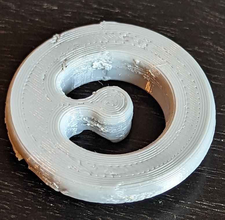
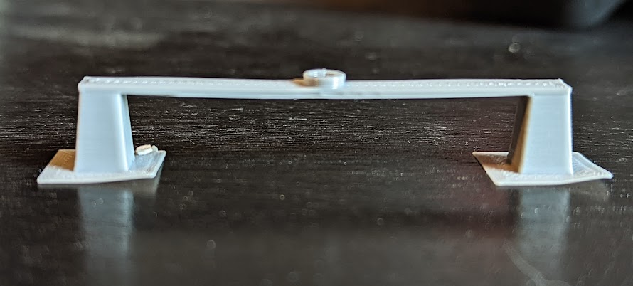
Shown below are two of the items I have made that required using PETG. The first is a trim panel hook for my Chevy Bolt that holds up the rear cargo cover. I needed to replace one and GM charges $20 for it. It costs around 25 cents to print one.
Chevy Bolt trim cover hook – top 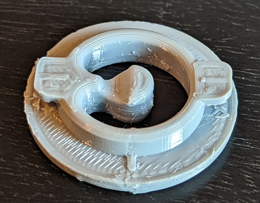
Chevy Bolt trim cover hook – underside 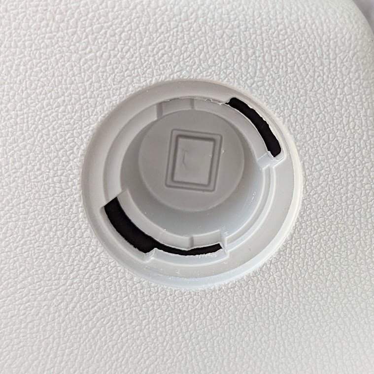
Chevy Bolt trim cover socket 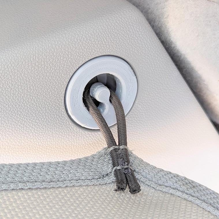
Chevy Bolt trim cover hook 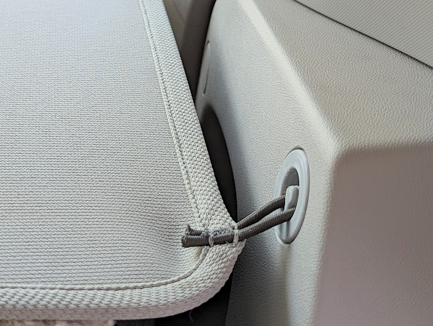
Chevy Bolt trim cover hook
I first printed one using PLA and it worked until the recent daytime temperatures hit the mid-70ºF range (and the car interior hit even higher). The PLA part started to give so I reprinted the one above in PETG and so far it has held up well.
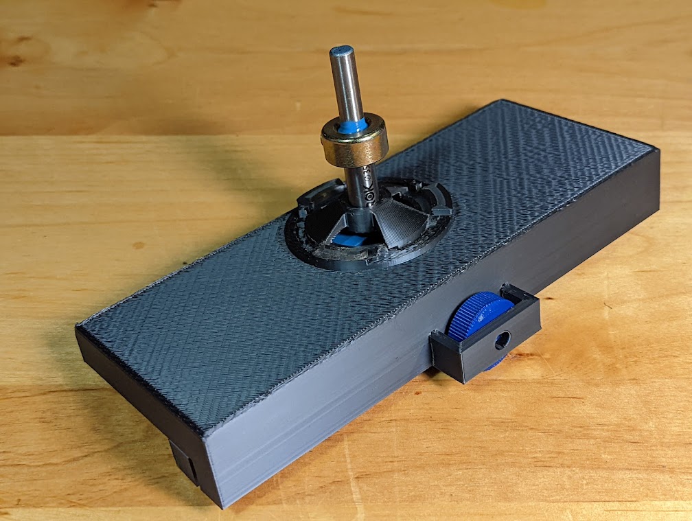
The second item is a hinge jig for drilling out the 35 mm diameter holes for European style cabinet door hinges. It needs to hold up to the spinning metal shaft of the Forstner bit it holds in place. I didn’t want to trust PLA for the task.
So now that you have seen a few examples of where you might want to use PETG material, let me dive in to how I tuned my printer to use it and some issues I encountered along the way.
The Ender 3 V2
The E3V2 uses a Bowden extruder, meaning that the extruder feeds filament through a long tube (the Bowden tube) into the hotend where it is melted on its way to the print nozzle. It works fine for printing PLA but I found it hard to get consistently good performance when printing PETG. The reason is that the hottend has to remain at a higher temperature to print PETG, as mentioned above. The default hotend on this printer is just barely up to the task. The default Bowden tube degrades quickly at temperatures much above 250ºF and will start to slip in and out of the socket, creating printing quality issues. There is a fix for this to help keep the tube locked into place but it doesn’t solve a second problem, which is that trying to feed the nozzle with the material necessary to keep PETG flowing requires a bit more pressure than with PLA and this is a strain on the Bowden setup. If you are doing limited PETG printing, you can get by with this setup but I knew I needed a longer term solution. That meant upgrading several parts of my printer.
Direct Drive Extruder
The first major upgrade I did was to upgrade to a direct drive extruder. As the name suggests, this eliminates having to push filament through a tube and uses an extruder mounted atop the hotend that feeds filament directly into the heating block and nozzle. I went with the Micro Swiss model that also included an all-metal hotend that provided a larger region over which the filament is heated. This also helps keep the flow as smooth as possible.
There are a lot of how-to pages and videos for this conversion. This is the one I found to be the most helpful.
Dual Z-axis Screw
Because the extruder motor now sits on the hotend, there is a little bit of extra weight on the X gantry. To offset any possible variations in printing height at various printing speeds and overall head and bed movement, I added a second Z-axis screw on the free side of the gantry. This solved some early direct-drive issues I had with print surface quality.
I ordered my kit from Creality and followed this video before doing it. It is an easy upgrade to do.
After doing both of the above upgrades, I had to go through an completely relevel my printer as well as recalibrate the extruder steps. Once that was done, it was time to find the settings best suitable for printing PETG filament.
Cura Slicer Settings
This is my general workflow that anyone on any type of filament-based printer can use to tune their setup, and for any type of filament.
Temperature Tower
Cura has a wide range of third part extensions that work with it and one of them is the Parts for calibration suite of 3D objects to print that will assist one in finding just the right settings to use. The first item I print when trying any new filament is a temperature tower. A good intro video on this extension can be viewed here.
There are a few included temp towers in this suite, one for PLA and one for PETG. They only differ in the range of temperatures used. The temperature tower prints a series of bridged zones (around 41 layers each) using a starting temperature and decreasing by a defined amount with each zone. For PETG, it starts at 260ºC and steps down in 5ºC increments to 230ºC. There will be one or possibly two temperatures in this range for which print quality looks acceptable. Looking at my output, I can see that 245ºC and 250ºC give reasonably good results. Notice the straightness of the bridge (no sagging from overheating, no poor structure quality from too low of a temperature). Also look at the bridge supports. There is a straight diagonal one on the left and an arched one on the right. They start to degrade as the temperature gets lower.
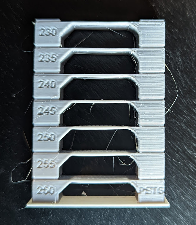
This print was done with a bed temperature of 80ºC, no supports and no brim. Furthermore, PETG is printed best with no part cooling enabled (0 fan speed). Exceptions on cooling are for the bridging portions or for overhangs and will be discussed below.
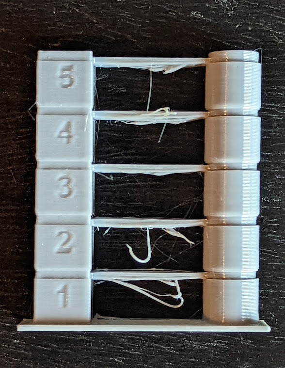
String Tower
The next object to print is a string tower test object. Like the temperature tower, this prints a series of bridges and shapes repeatedly over several different zones. Stringing mainly occurs when the print nozzle has to jump from one part of a print to another with a noticeable gap between the two regions. Stringing occurs at sharp corners as well as from curved surfaces, two of the main features of this test. Retraction is where the extruder pulls back on the filament to prevent it from oozing out of the nozzle. How much distance to pull back, and how fast, are number this print was designed to find.
For this test print, I was varying the retraction distance from one zone to the next. Direct drive extruders typically do well in the range of 1–2 mm whereas Bowden systems will require larger retraction distances (5–7mm). Not only does this slow down the print time but it shows another weakness of the Bowden system over using a direct drive one. I started with a retraction distance of 1.0 mm and increased by 0.2 mm from one zone to the next. My retraction speed for this was set to 30.0 mm/s (normal print speed is 50.0 mm/s). Zone 3 ended up showing the least amount of stringing even though the quality was pretty good at all settings. I didn’t do a separate retraction tower test for the retraction speed setting as I was happy with the current speed used on this test. Thus my retraction settings for PETG are 1.6 mm at 30.0 mm/s.
Dome Test
This test is not part of the Parts for calibration suite but is something I am including since I need to print a few parts that resemble it. In the printing of that part, I came across an interesting setting that affected the surface quality of a print along the z seam. The test part is a 20mm diameter cylinder with a 10mm radius dome on the top. The z seam showed noticeable gaps as each new layer started to print (left object). A setting that fixed this (right object) was to uncheck the “Outer Before Inner Walls” option in the “Walls” section of the CURA settings. This is normally checked, meaning that when a new layer is started outer walls are printed before inner walls. Because a retraction happens at the start of each new layer, the gap appears as the nozzle needs material to start flowing again. The reason you would normally want outer walls to print first is for dimensional accuracy. Printing outer walls first locks the dimensions in while inner walls are then more constrained. Printing the inner walls first has the tendency to cause outer walls to offset ever so slightly to the outside of the print. However, in this case both of these cylinders measured 19.93 mm and 19.98 mm in diameter, within the tolerances of what I needed. The z seam on the right made for a much better overall surface quality.

Bridge Tests
Bridging is where you need to print with no base support structure in place. There are many instances where you want to do this and it is one of the amazing abilities of 3D printers. Getting the settings right seems to be a problem for many hobbyists out there. The first thing I print is a simple 50 mm bridge between two separated support towers. This test prints in about 15 minutes so it provides a fast way to dial in basic settings. Already you could have played with some of the settings when printing either the temperature tower or the string tower above but I do this separately to avoid messing with too many parameters all at once.
The 50mm bridge test isn’t part of the Calibration for parts suite but something I found on Thingiverse. The design is simple enough that you could do this with just about any design app within a few minutes. The settings that are most important for bridging are reduced print speed, increased cooling (first layer of a multi-layer bridge), and possibly reduced flow out of the nozzle. Cura contains experimental bridge settings that are quite well suited for this. Checking the box to enable them will allow you to set separate print speeds, flow, density, and fan speeds for sections of your printed object requiring bridges. Furthermore, if those sections contain multiple layers, you can set a second and third set of these parameters for the next layers.
There are multiple layers to the bridge in the test print above. For the very first layer of the bridge you want to slow down the print speed and ramp up the cooling as much as possible. Normal print speed is 50 mm /s but I slow it down to 10 mm/s for the first bridge layer. I also have the flow set at 50%. I left the density unchanged. As already pointed out, I print PETG with a part cooling fan speed of 0 but for the first bridge layer I change this to 100%, maximum fan speed. You want the material to harden in place as quickly as possible. The second bridge layer can print at a faster speed and with reduced cooling since you now want to build up the support and have the material adhere to the previous layer. Cooling is reduced and flow is increased. Finally, for the third layer I’m almost back to normal settings. Below I’ve listed all the settings I use for bridging. Note that the first parameter helps Cura know where a bridge begins, the Minimum Bridge Wall Length. I have this set to 0.0 mm so that overhangs end up being treated like bridges and I am able to print quite a few parts without requiring the additional printing of supports. It doesn’t always work but I haven’t hit any issues with leaving this setting at 0.0 mm either.
Enable Bridge Settings: checked
Minimum Bridge Wall Length: 0.0 mm
Bridge Skin Speed: 10.0 mm/s
Bridge Skin Flow: 50%
Bridge Skin Density: 100%
Bridge Fan Speed: 100%
Bridge Has Multiple Layers: checked
Bridge Second Skin Speed: 15.0 mm/s
Bridge Second Skin Flow: 100%
Bridge Second Skin Density: 75%
Bridge Second Skin Fan Speed: 40%
Bridge Third Skin Speed: 30.0 mm/s
Bridge Third Skin Flow: 100%
Bridge Third Skin Density: 80%
Bridge Third Skin Fan Speed: 0%
After the 50 mm bridge test looks satisfactory, I go ahead and print the full bridge test part from the Cura extension suite just to make sure all is well. This prints a series of bridge from 10 mm to 50 mm in length and is a great test of the settings dialed in thus far.
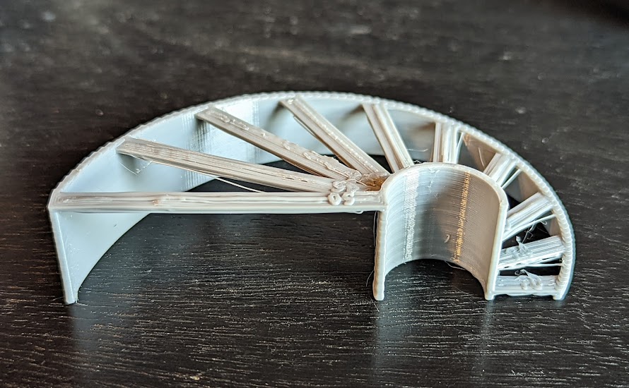
PETG – Bridge Test – quarter 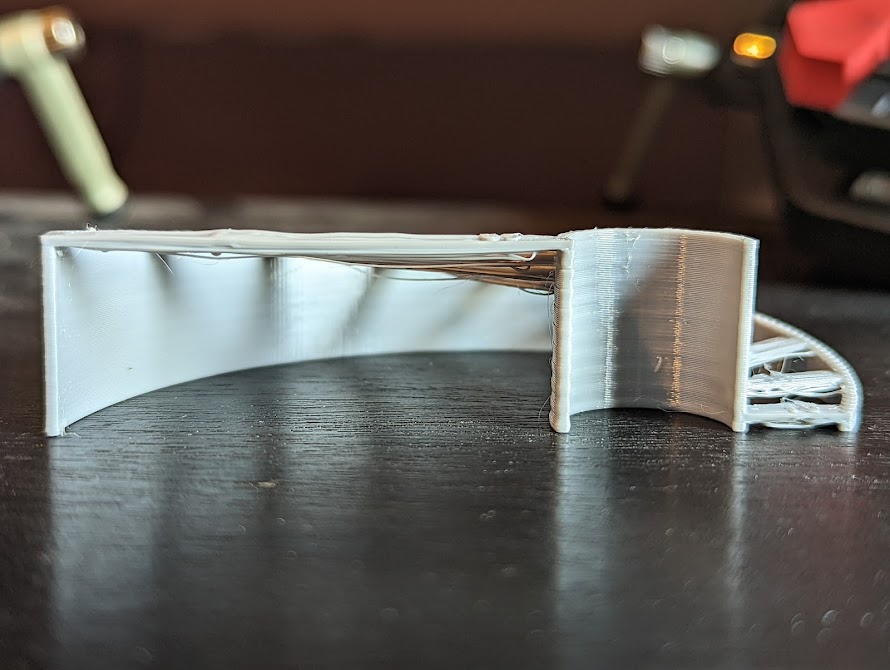
PETG – Bridge Test – Side 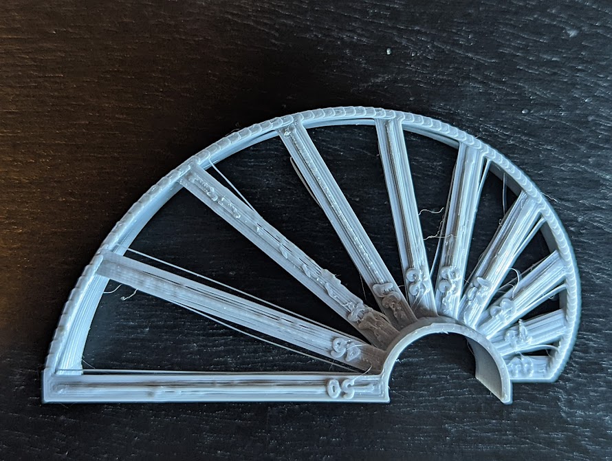
PETG – Bridge Test – Top
Finally, with all of these settings finally nailed down, I do one more test to see how well overhangs are handled. This doesn’t tell me what other settings to check so much as it gives me an idea for when I should enable supports or not for some prints or for some portions of prints. This test is the Overhang Test from the Parts for calibration suite.
PETG – Overhang Test 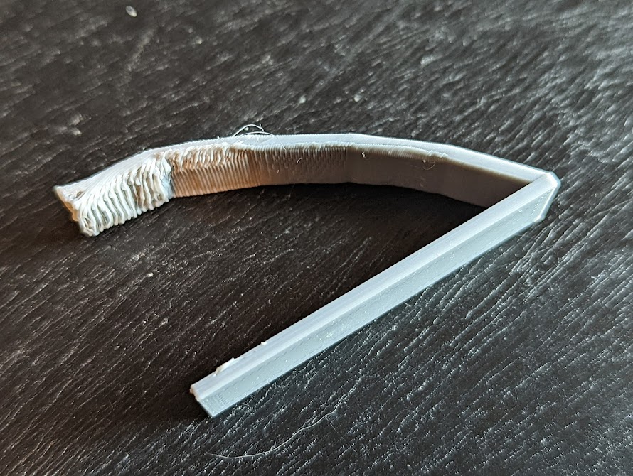
PETG – Overhang Test
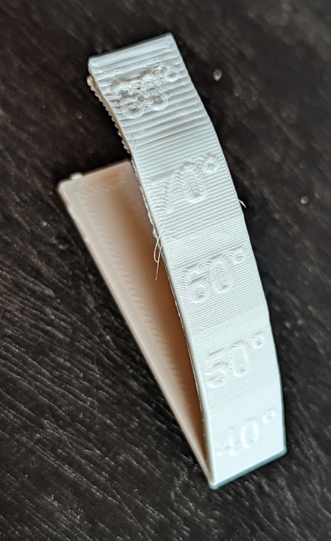
Print this with supports disabled. It shows how overhangs are printed starting at a surface inclined to 40º, then at 50º, and so on up to 80º. 90º would be bridging but with one side left unsupported, pretty much impossible. As you can see, my setup handles overhangs in PETG pretty well up to about 70º. The top surface of the 70º section is okay and beneath is borderline acceptable but not horrible. 80º is unacceptable all around.
Conclusion
There you have it. This is my workflow for tuning Cura to get the best quality prints out of a new filament, PETG in this case. Below I have listed the entire set of important parameters I have set inside my Cura profile for this printer and filament. I’m still looking for ways to improve the overall surface quality and I’m far from done with playing around with other settings I’ve read about but haven’t used yet.
Ender 3 V2 Direct Drive Extruder Cura Settings for printing PETG filament
Quality
layer height: 0.2 mm

Walls
Outer Before Inner Walls: unchecked (smoother z-seam)

Material
Material temp: 250ºC
Bed temp: 80ºC
Flow: 100%

Speed
Speed: 50.0 mm/s
Wall Speed: 25.0 mm/s

Travel
Enable Retraction: checked
Retraction Distance: 1.4 mm
Retraction Speed: 30.0 mm/s
Retraction Prime Speed: 15.0 mm/s
Retract Before Outer Wall: checked (reduces surface blobs)

Cooling
Regular Fan Speed: 0%
Maximum Fan Speed: 100%

Experimental
Enable Bridge Settings: checked
Minimum Bridge Wall Length: 0.0 mm
Bridge Skin Speed: 10.0 mm/s
Bridge Skin Flow: 50%
Bridge Skin Density: 100%
Bridge Fan Speed: 100%
Bridge Has Multiple Layers: checked
Bridge Second Skin Speed: 15.0 mm/s
Bridge Second Skin Flow: 100%
Bridge Second Skin Density: 75%
Bridge Second Skin Fan Speed: 40%
Bridge Third Skin Speed: 30.0 mm/s
Bridge Third Skin Flow: 100%
Bridge Third Skin Density: 80%
Bridge Third Skin Fan Speed: 0%

Recent Comments