The Bobcat CT235 is alive again!
Our Bobcat CT235 with only 977 hours on the engine broke down on 27 April 2026 after a coolant hose blew. My suegro bought this tractor used for his landscaping business around 2015 or so with just over 500 hours on the engine. Since then it has been used for various landscaping jobs as well as on the family ranchito for cleaning out cattle stalls, and the goat and sheep stalls, as well as moving and stacking 3’x3’x8′ bales of hay when they arrive. I have done routine maintenance on it, including oil and coolant changes, air filters, and an alternator replacement a few years back. It surprised me when this recent event happened.
I was using the tractor at the end of April this year when the engine suddenly lost power and then shut down in about 45 seconds. After climbing down to see what was going on, I noticed the pool of coolant in the dirt and after poking around beneath the hood, I found a burst coolant hose.
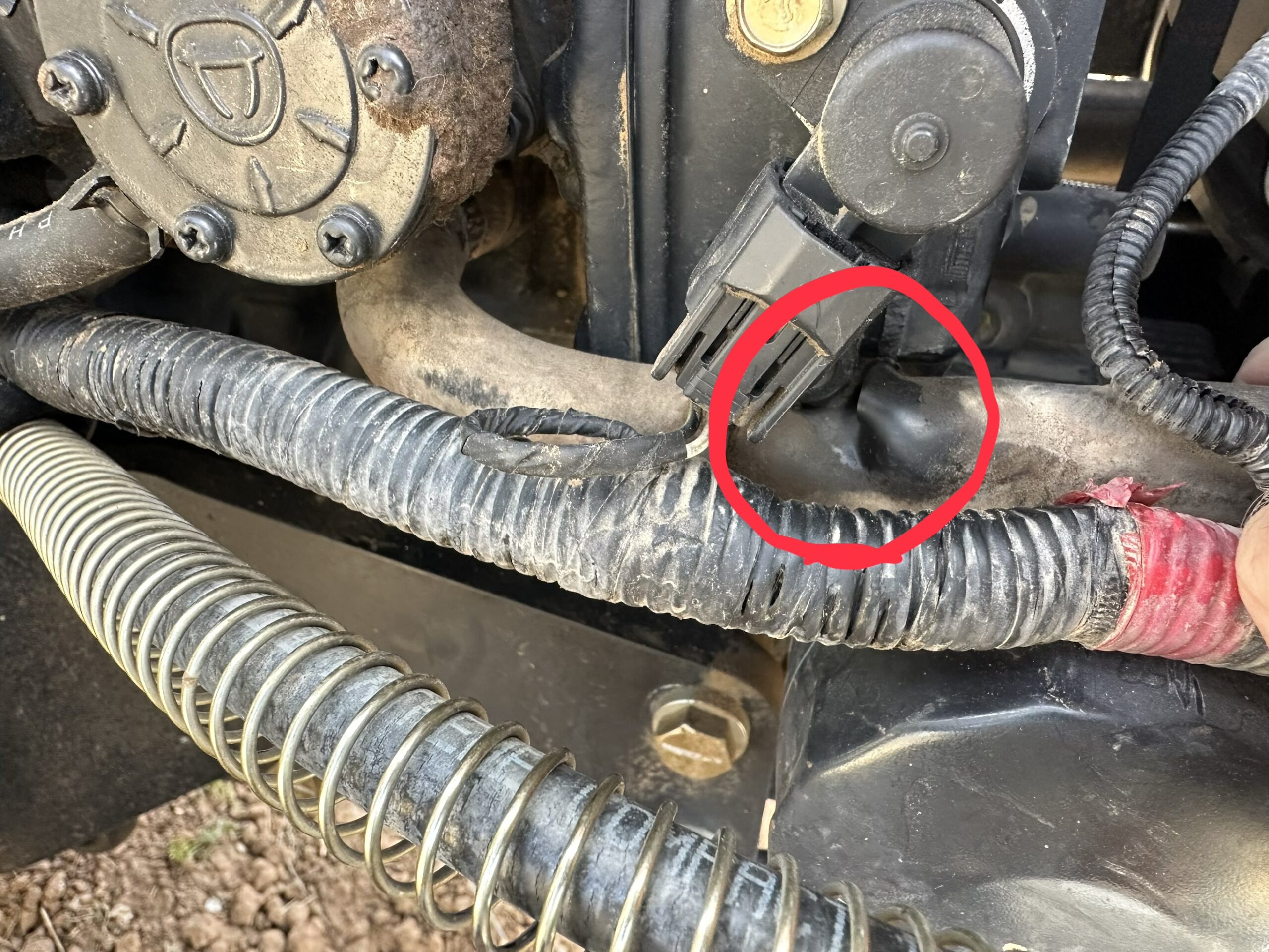
I don’t recall seeing the temperature gauge climb above normal, but I may also have been distracted by the engine suddenly failing. I was hoping that the fix would be as simple as replacing the hose, refilling with coolant, and getting back to work. The hose arrived a few days later and after installing it, the tractor failed to start. It would crank and crank for as long as the battery would allow it but it simply would not turn over. One thing I notice was how easy the engine turned over, meaning that it at least hadn’t seized.
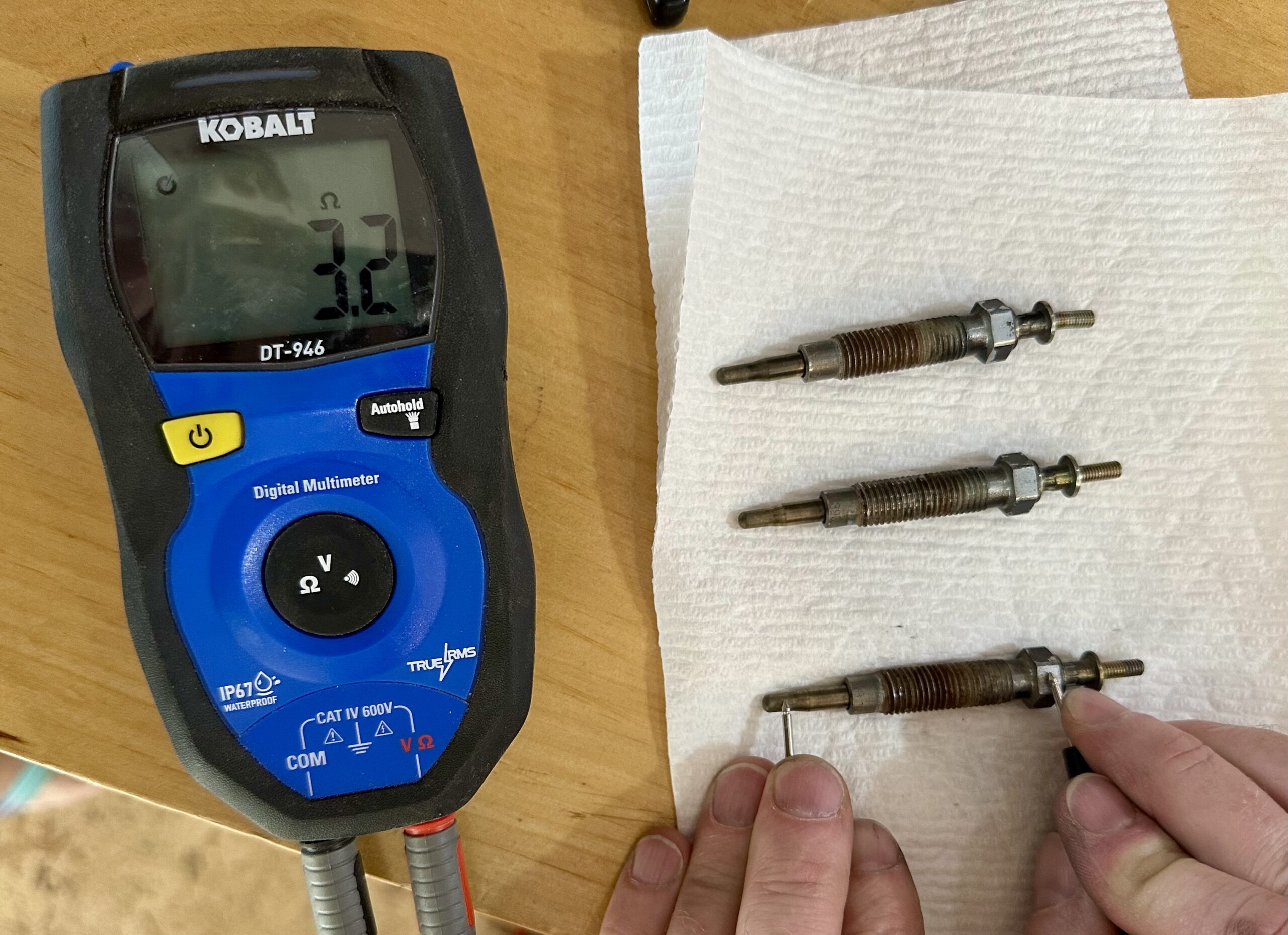
I checked out the easy things first. All fuses, relays, and electrical connections were good. The glow plugs were all receiving 12V. There was no oil leaking anywhere, especially from the cylinder head. The oil looked good, with no sign that any coolant was mixed in with it. Next I pulled out the fuel cutoff solenoid and made sure it was okay. Finally, I pulled out the glow plugs to check their condition. The plug on cylinder #3 came out using just my fingers, as if someone had previously removed it and failed to put it back in completely. Other than that, all three looked worn but not bad. However, when I measured the resistance on them, the one from cylinder 2 showed zero resistance and the one from cylinder 1 read 3Ω. It should have been around 0.5 Ω. I ordered a new set of glow plugs and continued testing in the meantime.
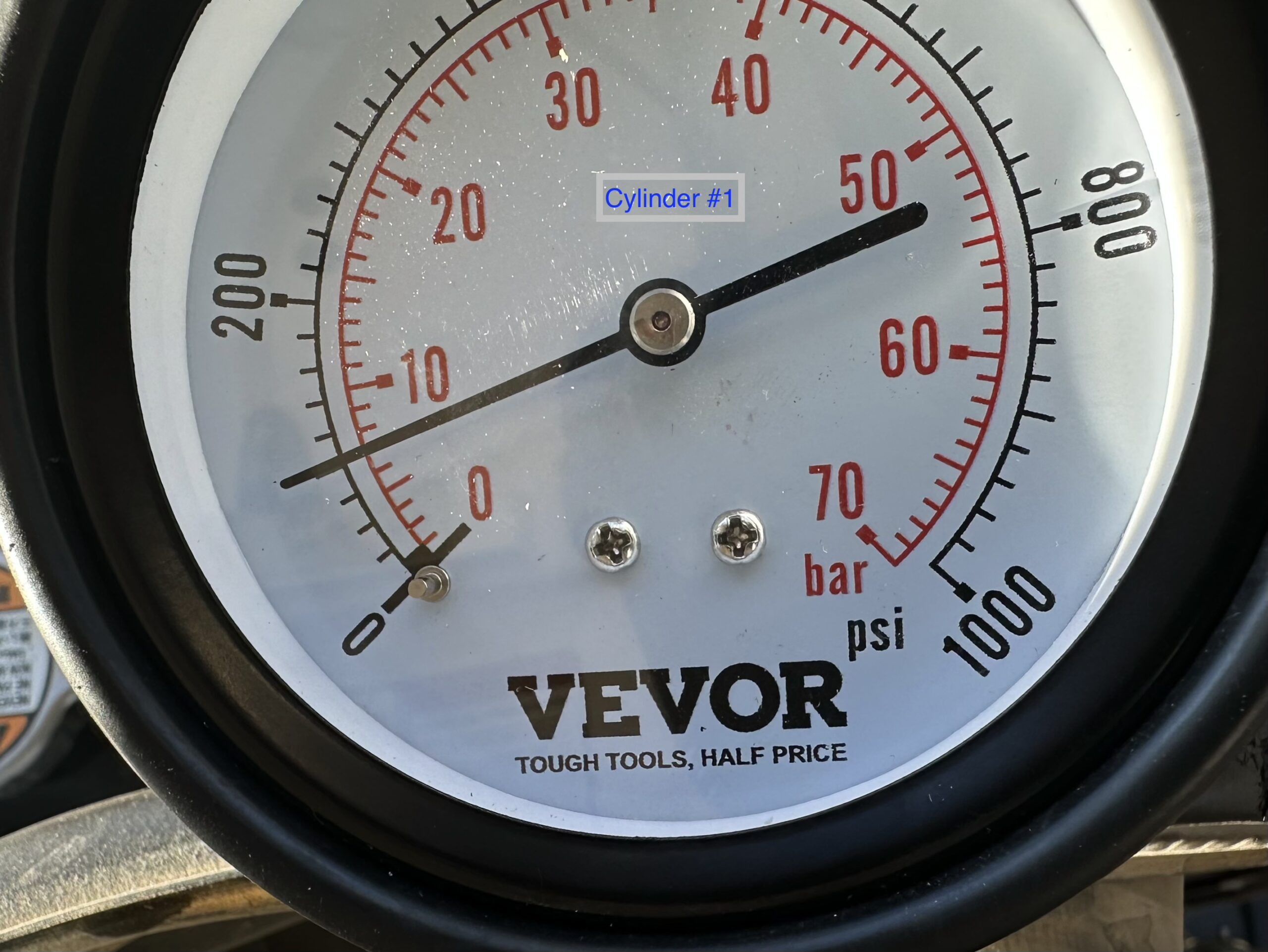
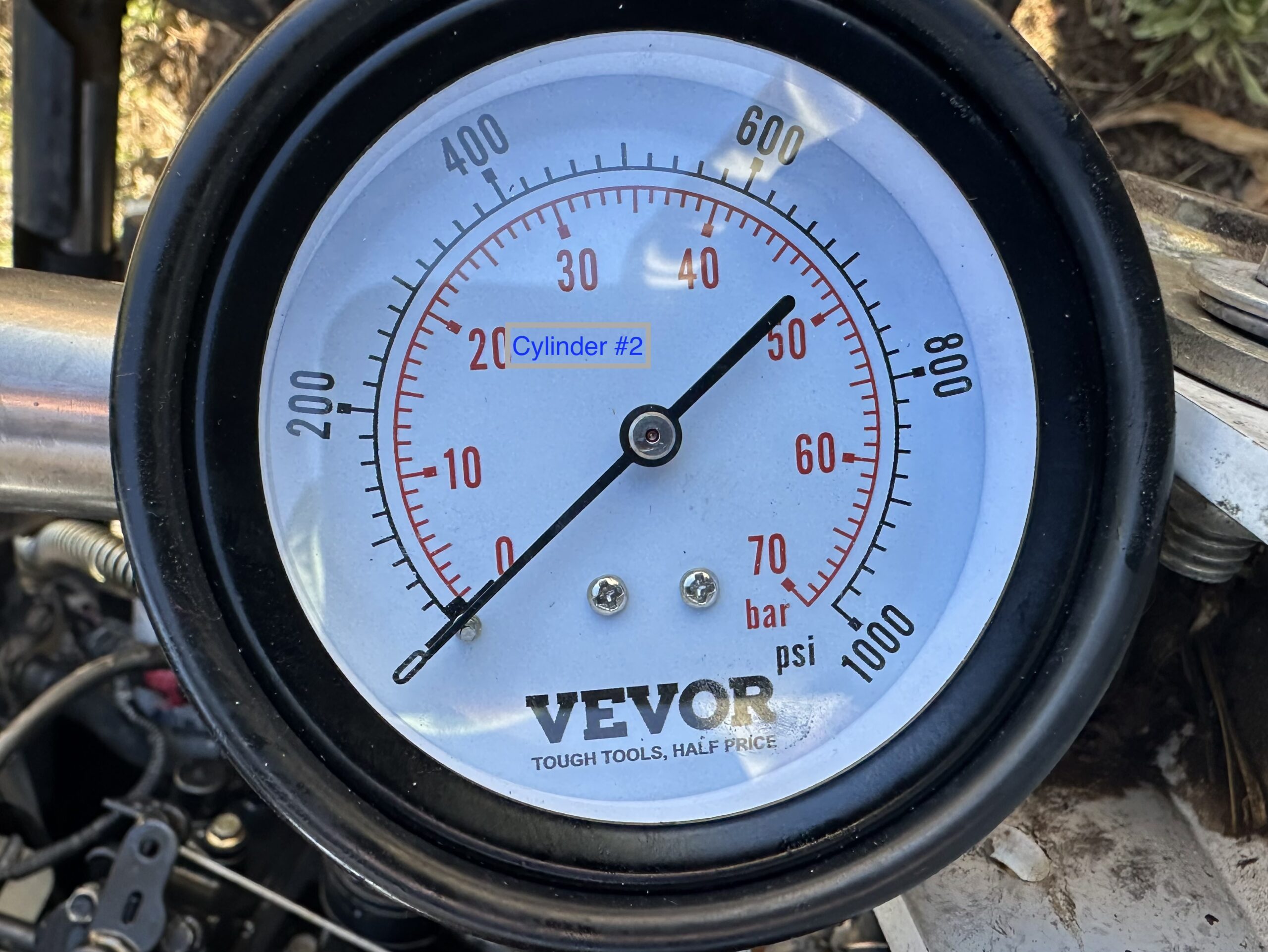
Since I was removing the glow plugs, I checked the compression in each cylinder. This gave me my first indication of serious trouble. According to the service manual, the compression should read between 469–540 PSI without an allowable limit of 370 PSI. Cylinder #1 read 100 PSI while cylinder #2 was dead zero. I was unable to measure the compression on cylinder #1 without removing either the engine, or the instrument shroud and fuel tank.
I knew I was now looking at having to remove the cylinder head but first, I measured the performance of the injector nozzles. The injector from cylinder #3 held pressure at 1850 PSI and delivered a clean jet at just above 2100 PSI. injectors from #1 and #2 did not hold pressure at 1850 PSI but did jet at just above 2100 PSI as well. The service manual says the jet should emerge at 2134 PSI. The nozzles were good enough that I didn’t have to do anything with them.
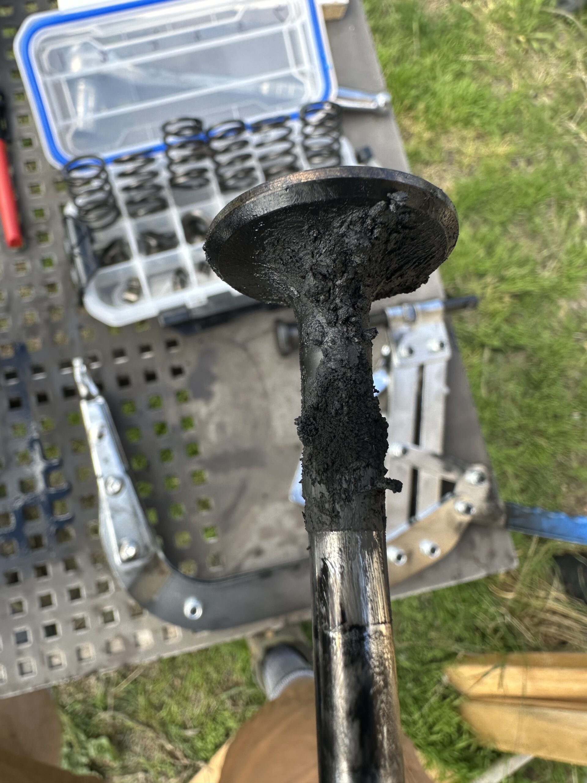
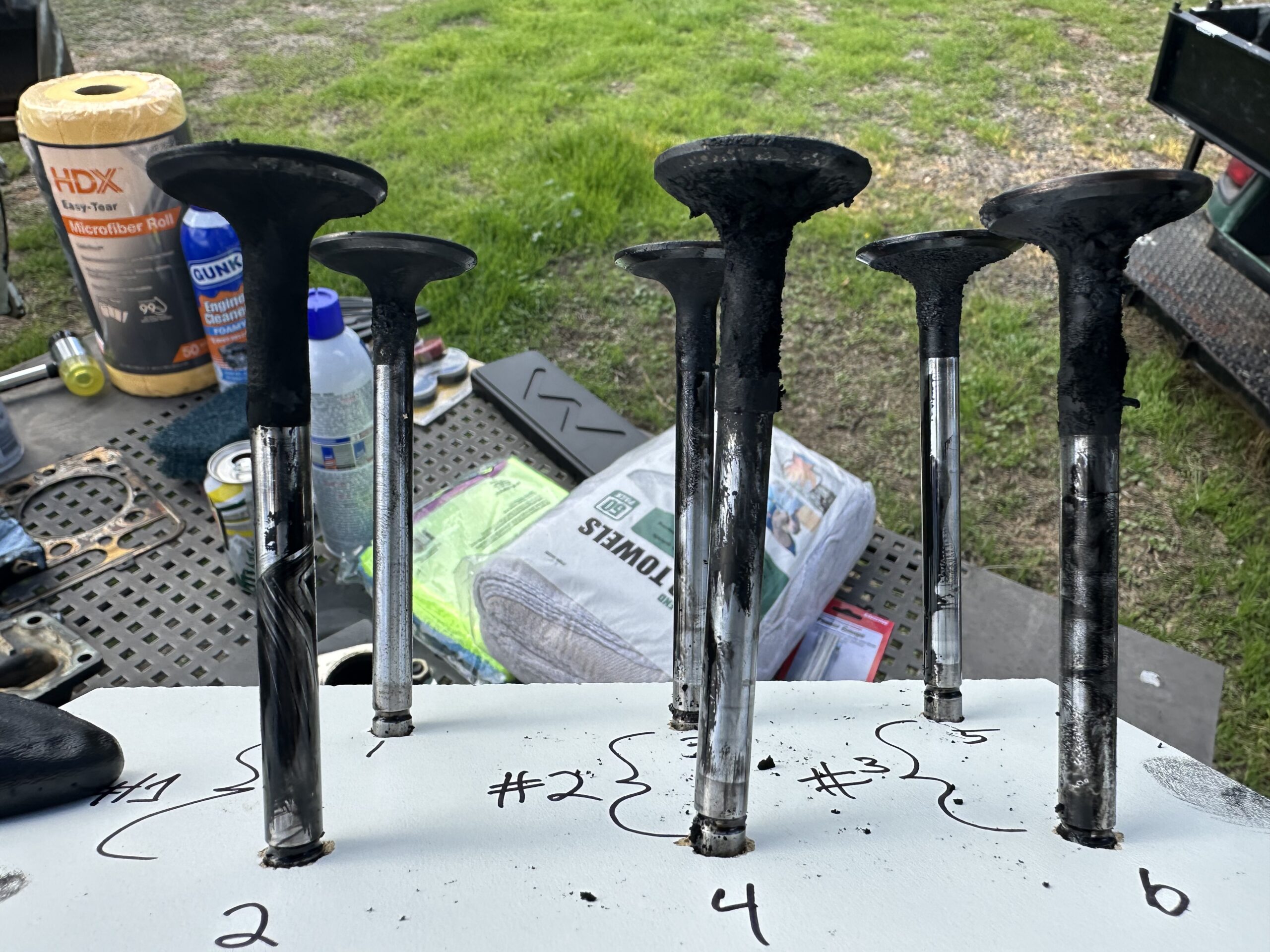
The tractor sat until the end of summer as I worked on finishing up a restoration on our Subaru Baja and other projects got in the way. Finally at the beginning of October I got around to finishing up the diagnostic work on the Bobcat. I removed the cylinder head and right away noticed that the valves were part of the problem. The ones from cylinder #1 and #2 were so corroded that they did not close all the way. I removed all the valves and set them aside to be cleaned later.
There was no sign of any issues with the head gasket even though I planned to replace it. The pistons, however, told a different story. Since I had the cylinder head removed, I also removed the thermostat housing and tested the thermostat using the heating-water technique. I found that the thermostat failed to begin opening until the water reached 190ºF. It should open much sooner than this, and out here at 6,300 ft where water boils at only 200ºF, it is likely the reason the pressure in the coolant system caused the hose to burst. Later on I also examined the radiator fins and cleaned away several years’ worth of hay and animal manure caked onto the front of the radiator. I suspect reduced airflow also caused some over-heating. Now back to the pistons.
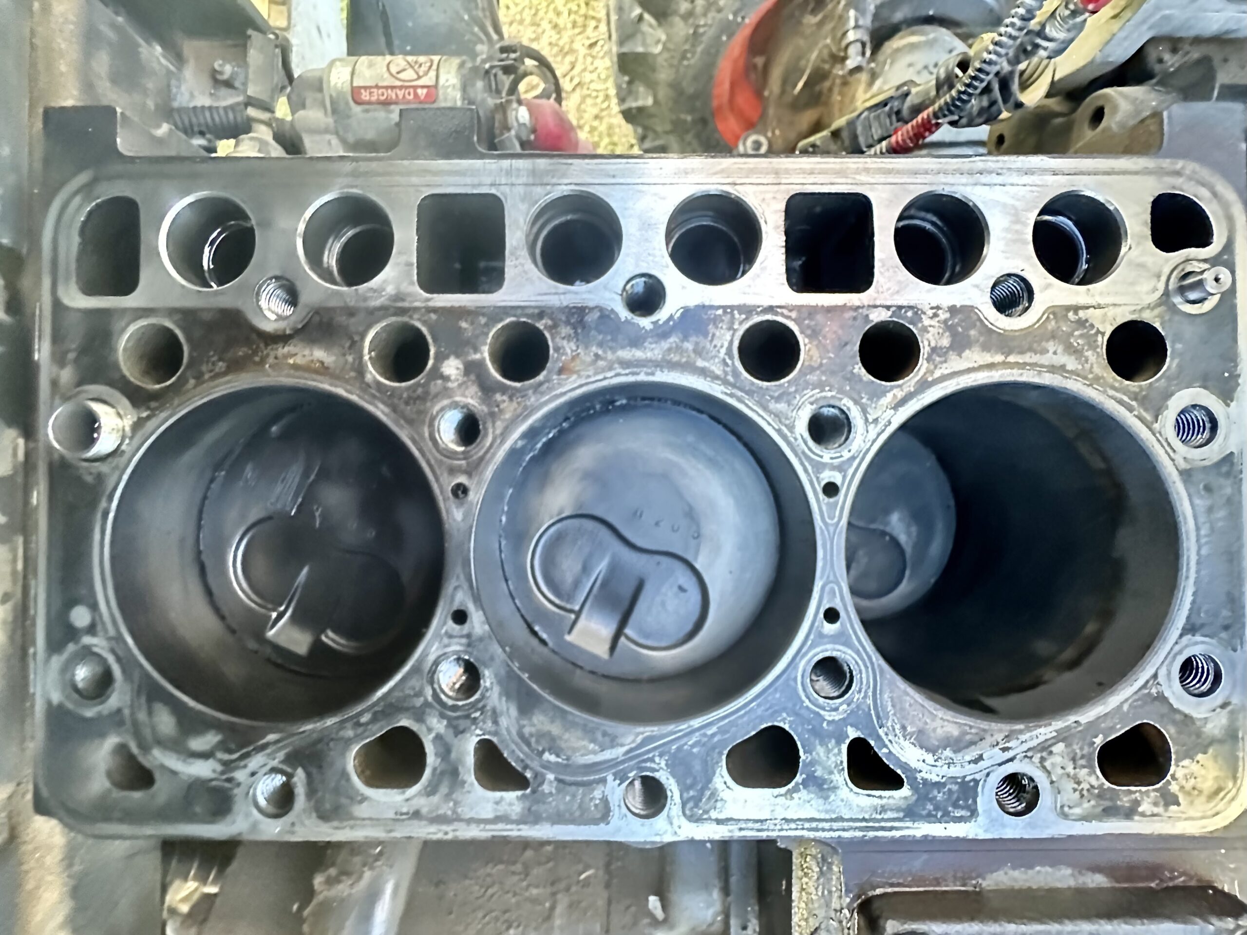
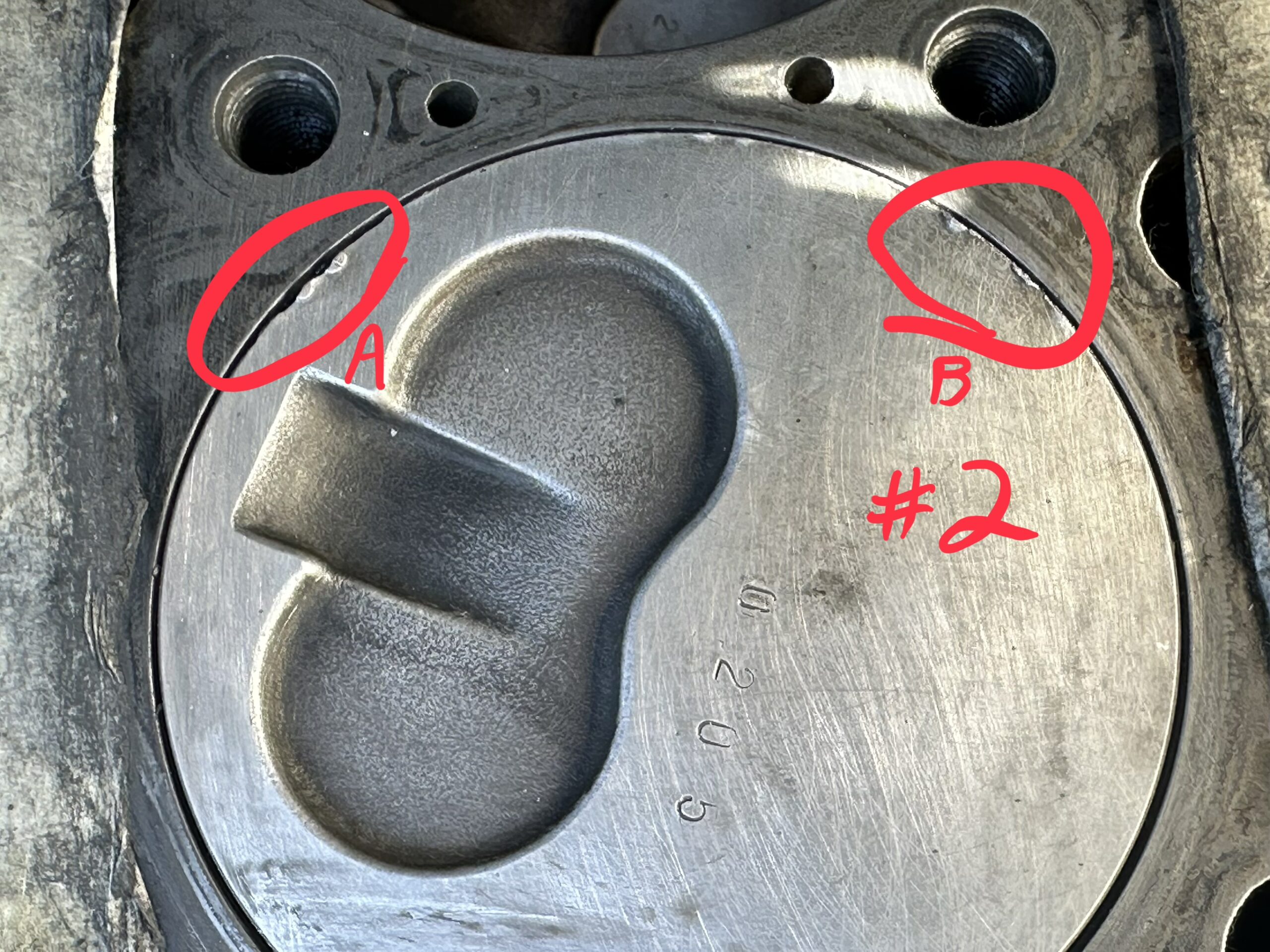
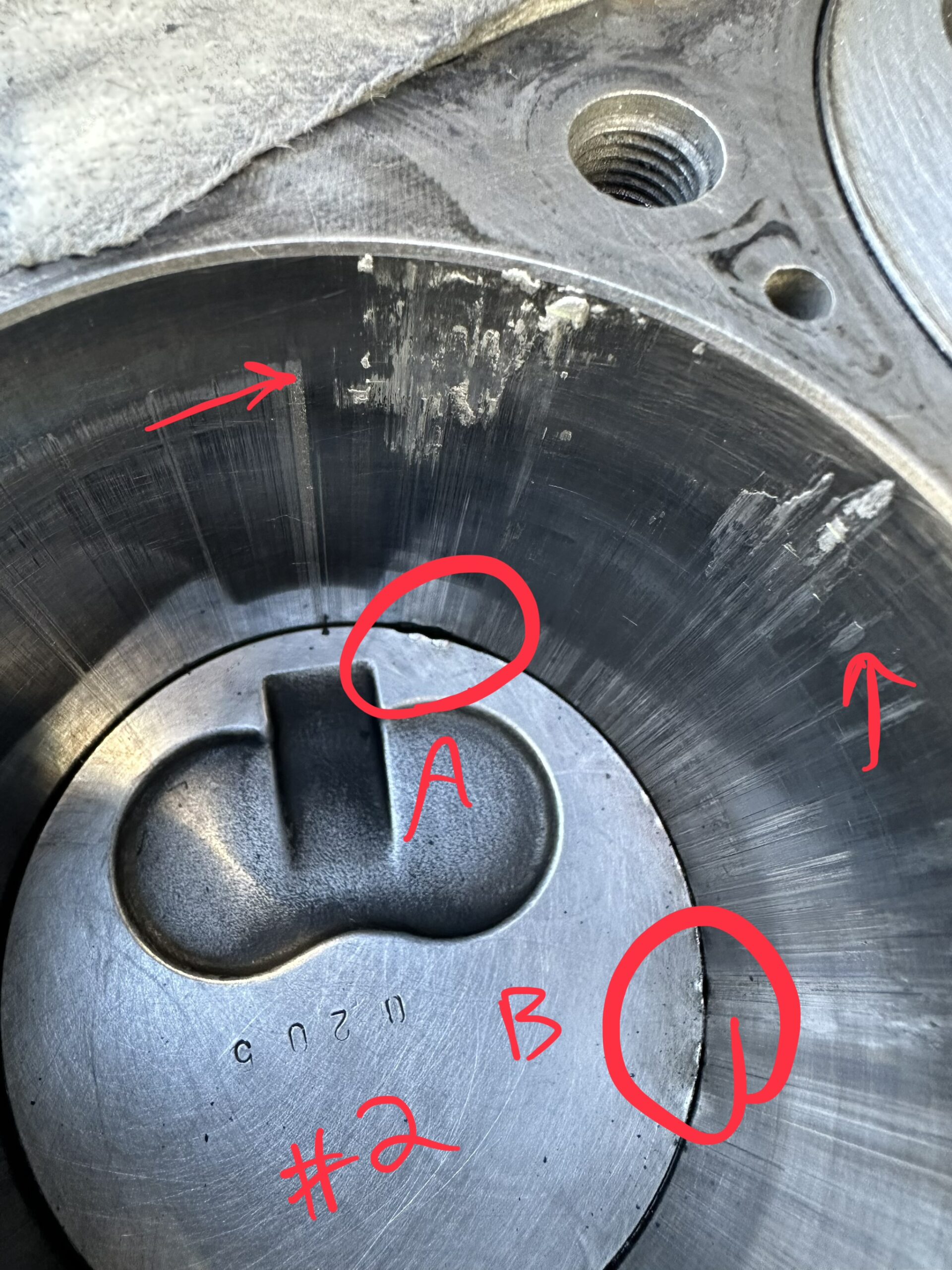
Piston #2, the middle piston, had visible signs of damage on the surface in two spots, labeled A and B in the photos. It seems like it had driven itself into the cylinder wall at one point or two. The metal on the surface of the cylinders seems to be from the piston. Removing the pistons involved removing the drive shaft in order to remove the oil pan and gain access to the crankshaft bolts. After removing them for further inspection, it was clear #2 needed to be replaced.
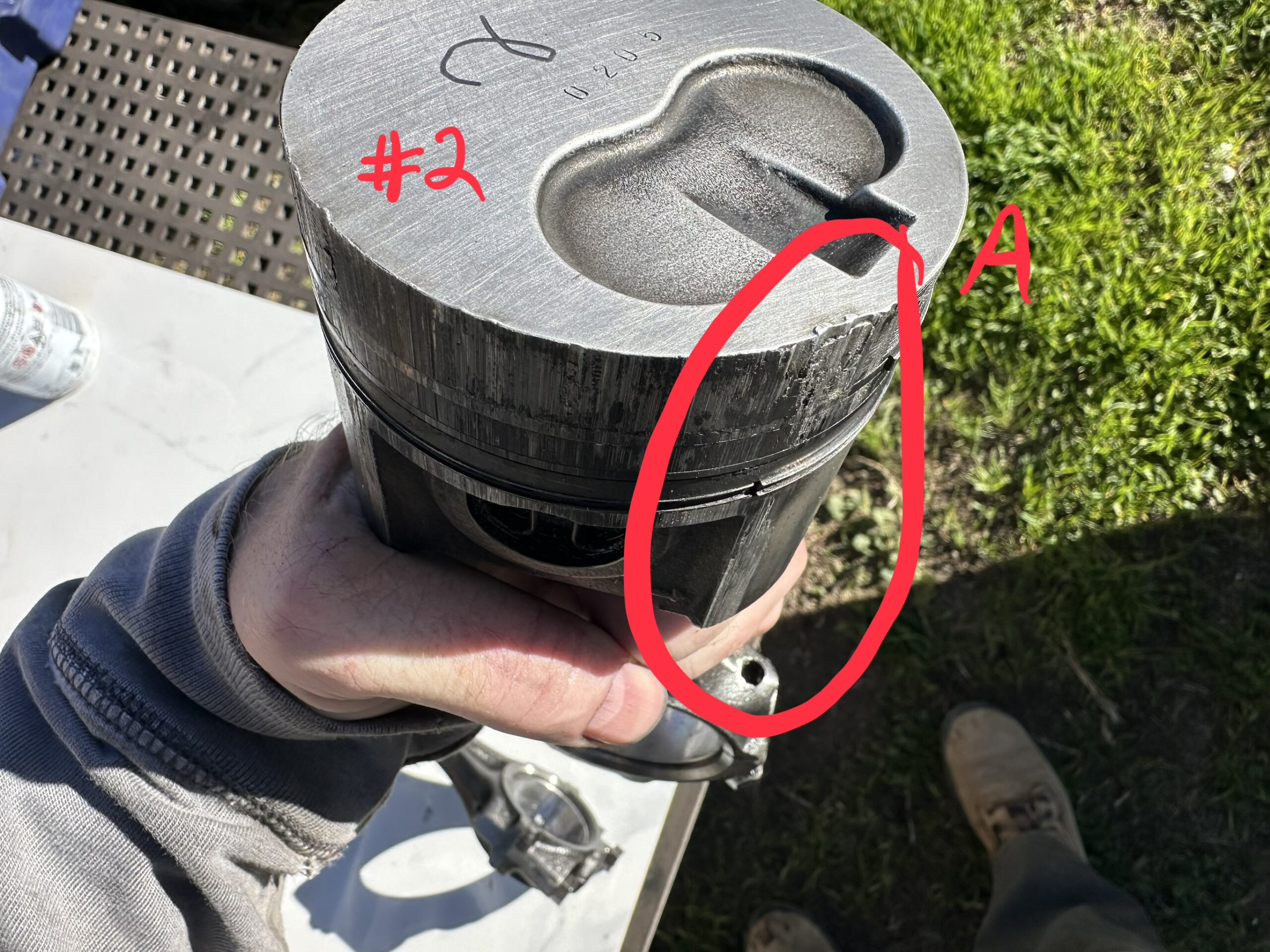
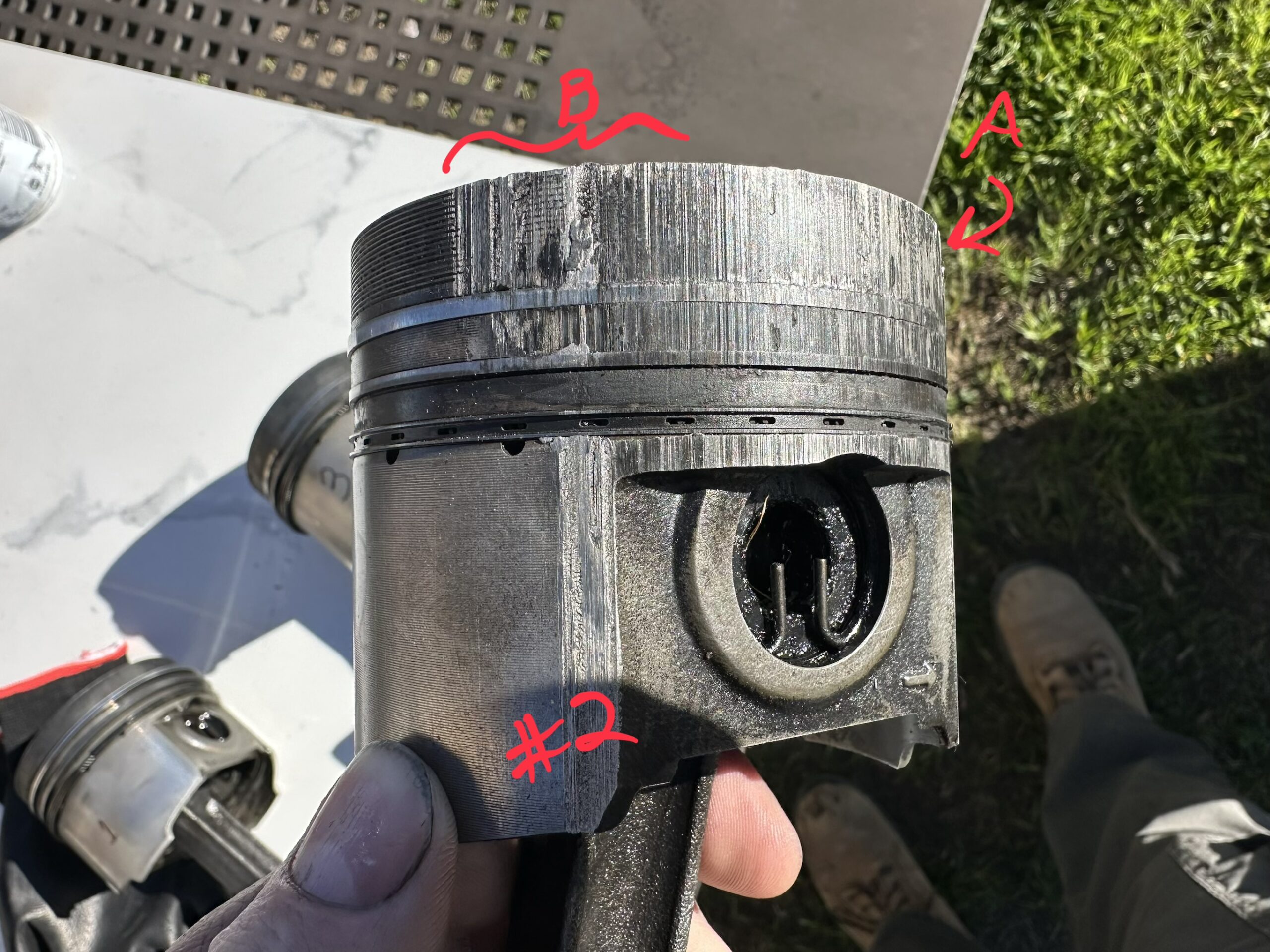
In addition to this damage, the piston rings were completely compressed and lacked any ability to seal against the cylinder walls. They were stuck within the grooves of the piston. Piston #1 also looked more worn than I would have liked and it also needed new rings. I ended up ordering a new set of three pistons and rings just to be safe. While waiting for those to arrive, I honed the cylinder walls and was surprised at how clean they came out. Even the gouging in #2 was less than I could get a fingernail into.
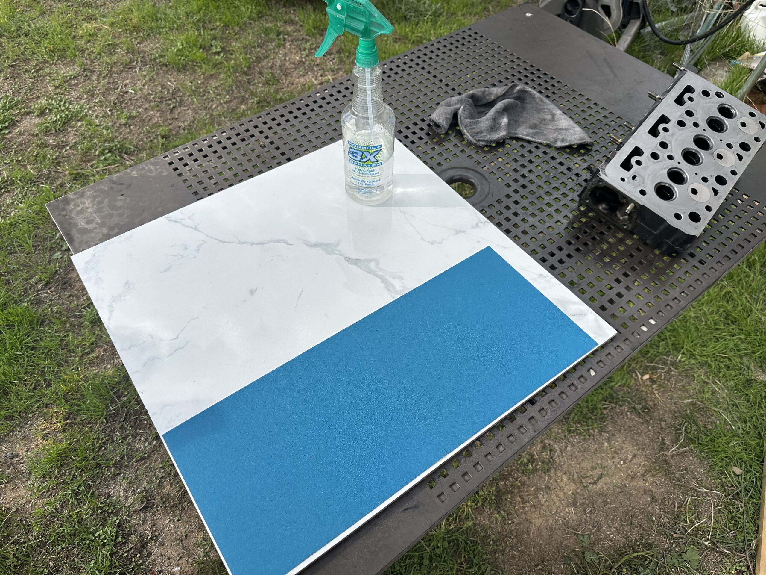
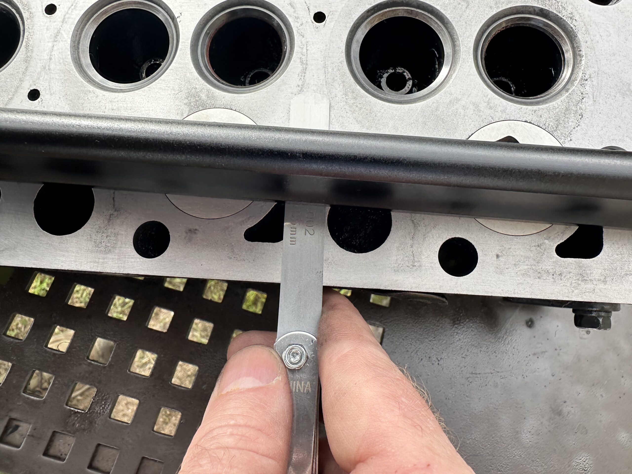
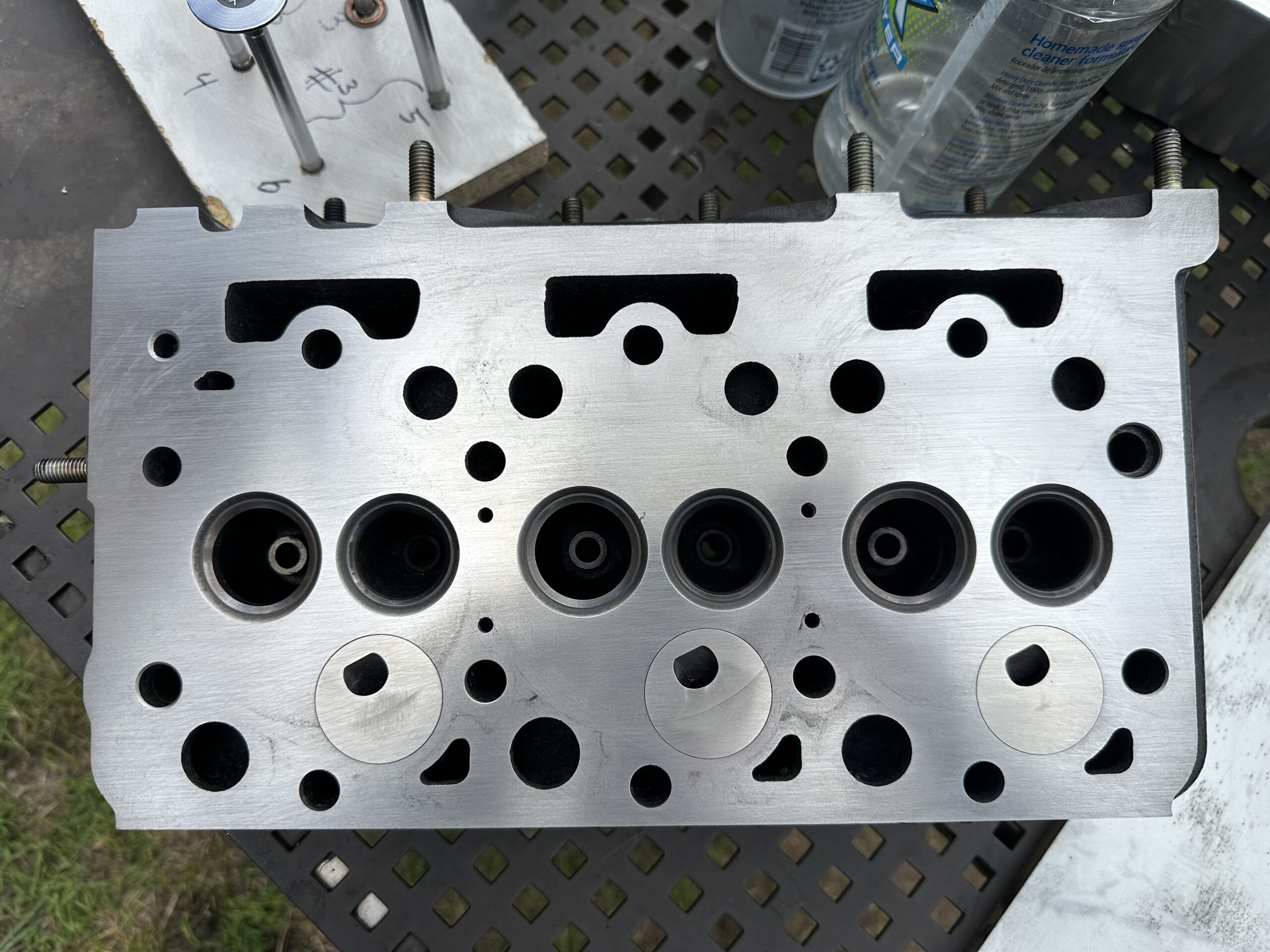
Next I thoroughly cleaned the engine block surface and the cylinder head so I could measure for flatness. The manual says there should be no gaps greater than 0.002 inches at any of the locations checked. The engine block was flat and there was no point where I could get a 0.002-in feeler under the straight edge. The cylinder head had minor warping. There were many places I could slide the 0.002-in feeler beneath the straight edge and a few that would even allow a 0.0025-in feeler. No spots would allow for a 0.003-in feeler. Since I had very little material to remove, I decided to resurface the head myself rather than take it to a shop. For this I used a very flat 2-ft x 2-ft marble tile with two sheets of 120-grit sandpaper adhered to it using 3M spray glue. After wet sanding for just over an hour, the surface was finally flat enough that it passed the 0.002-in feeler gauge test. The crucial idea is to move the head back and forth without letting it move off the paper along any edge, and to not press down on it at all. Let its own weight do the work.
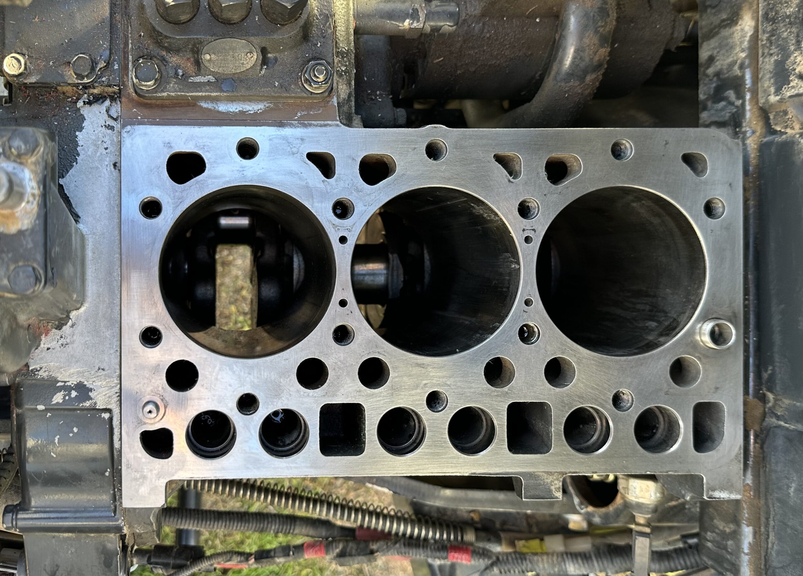
The piston rods and bearings, as well as the crankshaft pins, were in great shape. While waiting for the pistons and a new thermostat, and a gasket set to arrive, I set about cleaning up the valves and re-lapping them. I cleaned up the valves using engine cleaner and a Scotch-Bride pad. I put the valves in a drill and spun them at slow speed in the pads while keeping them lubed with cleaner. Afterwards, I repeated the same process using 1,000, 2,000, and 2,500-grit sandpaper and engine cleaner. The chrome finish on the stems was in great shape after it was all done. Finally, I lapped the valves in their respective seats using a traditional lapping tool and grinding paste.
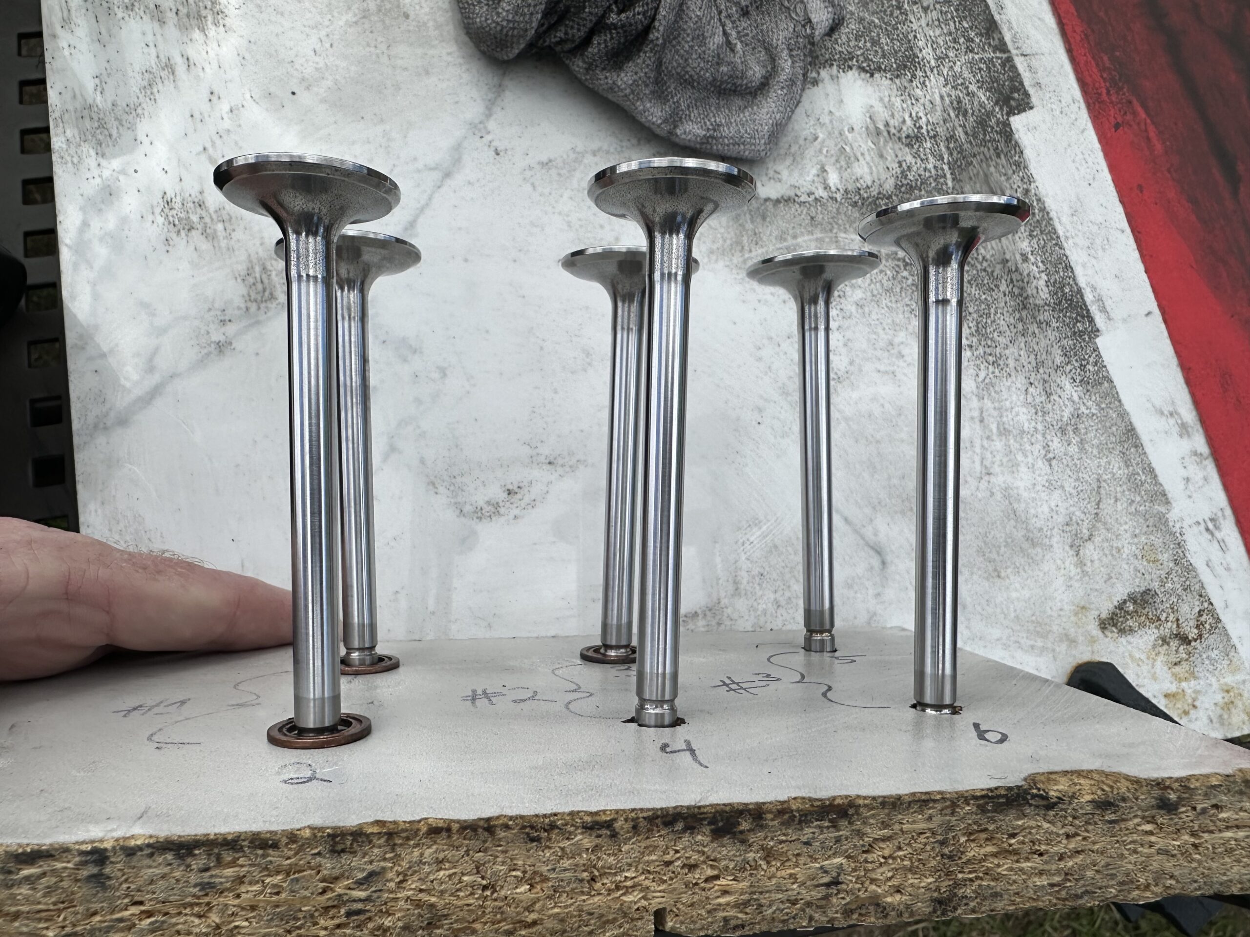
With everything cleaned and resurfaced, the pistons and gasket kit arrived. I spent two and a half days methodically assembling everything. I started with the pistons and new rings and installed them onto the crankshaft. Next I installed the valves using the new seals from the gasket kit. With the valves installed I could place the new head gasket in place and the cylinder head into position. Then it was time to torque down the head bolts using the procedure in the service manual. Each bolt was tightened to about 10 ft-lbs in the correct sequence, then to 20.9 ft-lbs in the same order. After that, each bolt was further turned by 90º, again in order. Finally, each bolt received an additional 80º turn. This was the most difficult part and I was certain I was going to snap off a bolt head.
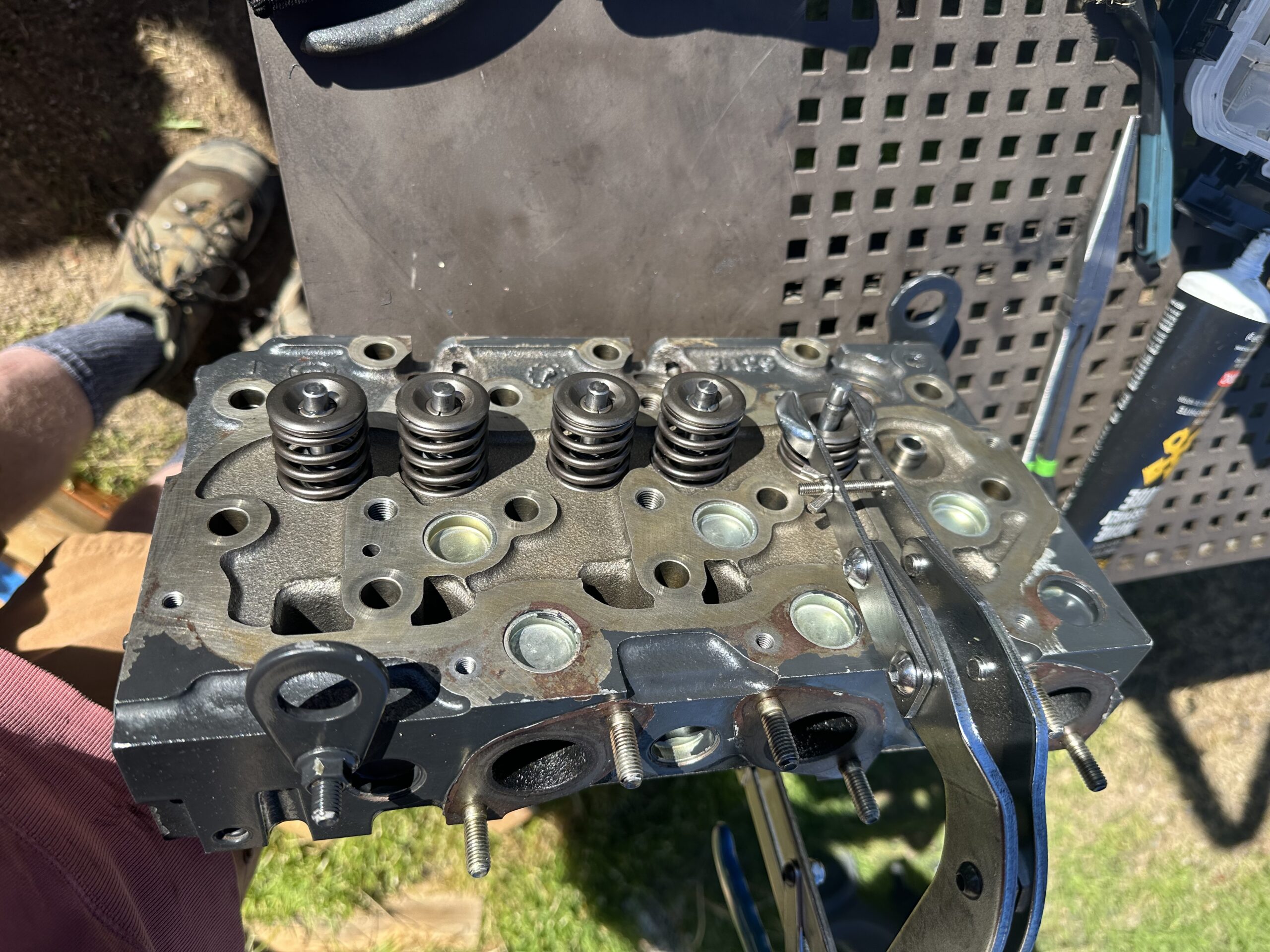
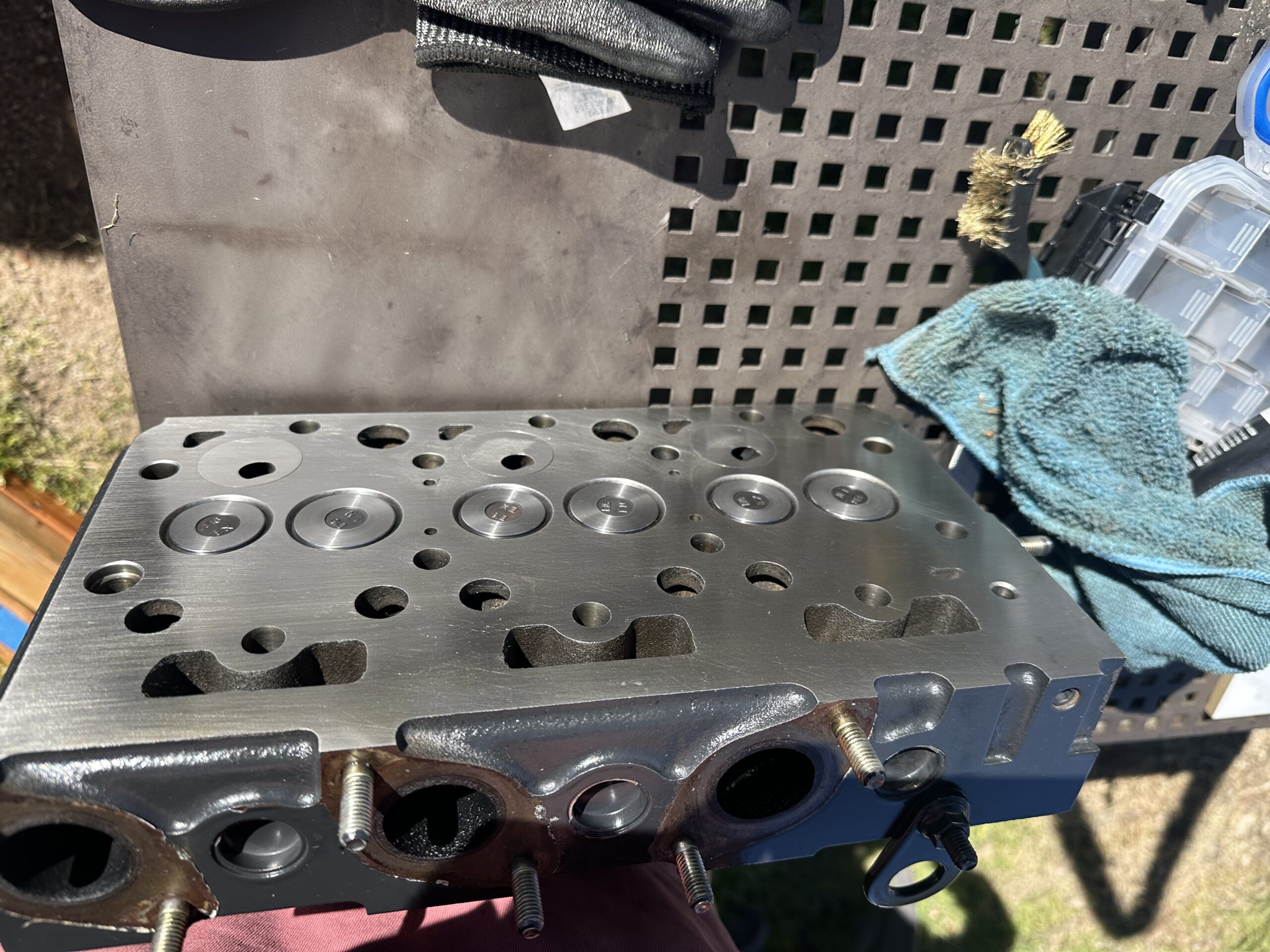
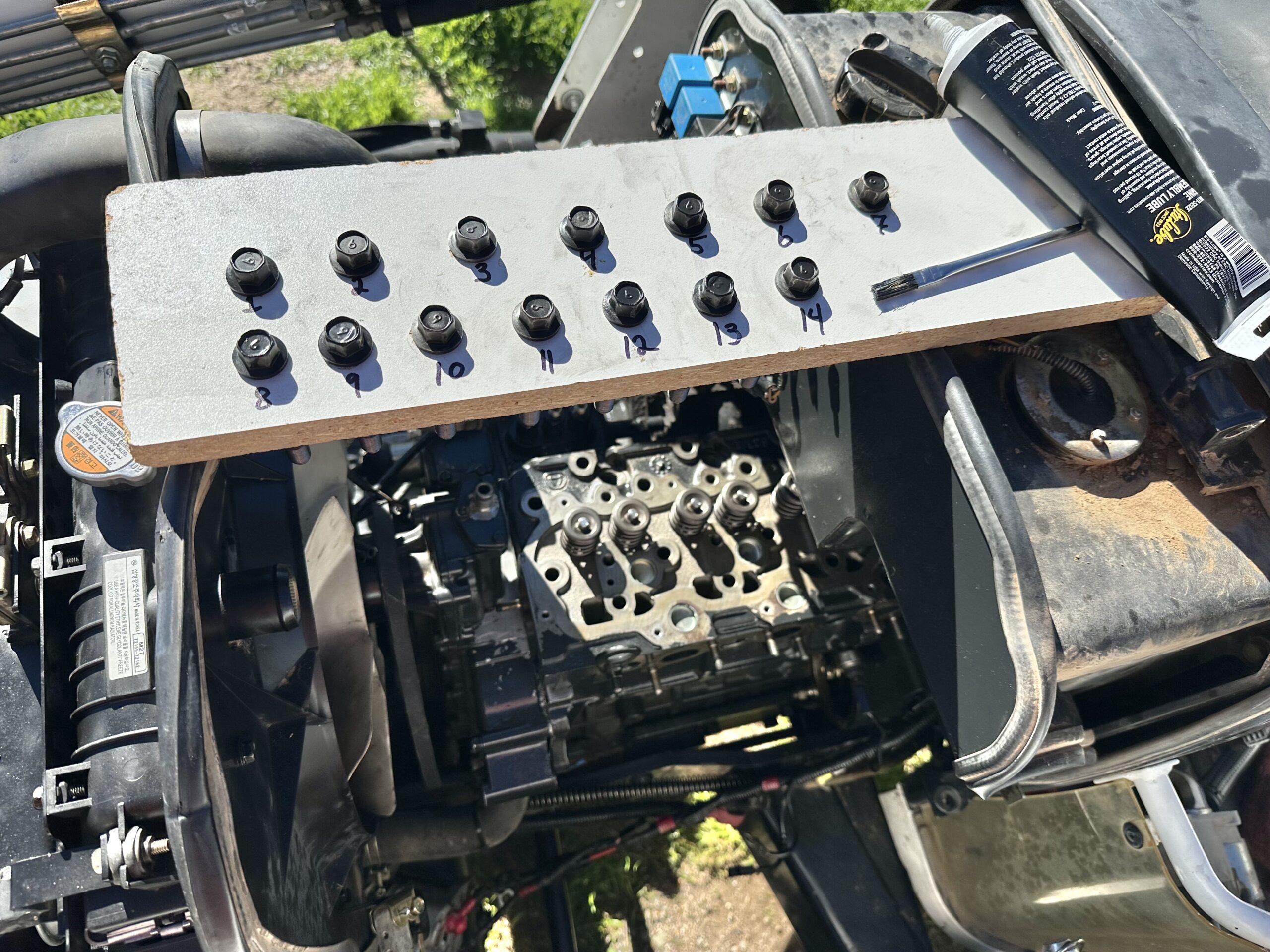
Once the cylinder head was installed it was time for the lift pins and rocker arms. There is a procedure for measuring and setting the valve clearance in the manual but for the life of me, I cannot find the view window they mention for seeing when the pistons are at top dead center (TDC). I left the valves as they were originally set and torqued down the rocker arm assembly, then installed the rocker arm cover with its new gasket. I have since heard from a few people on a way to set the valve clearance without needing to view the timing marks so that will be another weekend project.
I reassembled the rest of the components around the engine and by sunset the third day of working on this, it was ready for a trial start. I filled the engine up with oil (and observed for any leaks), filled up the radiator with fresh coolant, and set the fuel flow to “on”. The tractor cranked for no more than a few seconds after the glow plug indicator lamp turned off, and the engine roared to life for the first time since April 27th.
I have since used the tractor for a few hours to turn over some compost piles and fill in some holes elsewhere on our property with some of the fresh dirt. It was a great feeling to have been able to do this with a basic home setup. I’ve listed below the special tools I used and the parts I ended up purchasing to complete it all. For the parts, the costs include any taxes and shipping.
The two most valuable sources were Southern Global Tractor Parts out of Wiggins, Mississippi, and Dykes Motors out of Collins, Mississippi. These two companies not only have reasonable prices on these parts, but they offer great online shopping experiences. They shipped immediately and communication with them has been quick and painless.
Tools
You’ll need a basic metric socket set, 1/4-inch and 3/8-inch for the most part, 1/2-inch 14 mm socket for the head bolts when it comes time to torque them down. The largest socket needed was a long 22 mm for the injector nozzles. I’ve owned my set for decades so I’m not including the cost here. You’ll also need a punch to remove a roll-pin in order to remove the drive shaft, which I also already owned. I already had the valve lapping tools but I’m including them here since they’re cheap and you may not have them. I used the smaller of the two and it was perfect for this small diesel engine. The lapping compound can be purchased from any auto part store. Despite the fact that I had to purchase the remaining tools, I know that I’ll be using them again so I’m not including them in the final repair cost either.
I didn’t mention it during the repair process but I used about 1/4th of a tube of assembly lube during the rebuild. This was for sliding the valves back into place as well as installing the piston rods onto the crankshaft and for coating the cylinder walls before putting the pistons into place. The threads on the cylinder head bolts were also given a light coat. You can use regular oil for this but I was working outside on days in temperatures between 45ºF and 60ºF and I didn’t want the oil to drain away before I was finished putting it all back together.
Parts
| Glow Plugs, 3 at $29/ea | $123.24 |
| Upper Gasket Set (includes rocker cover gasket, head gasket, valve seals, and all the other replaceable gaskets above the oil pan) | $271.24 |
| Pistons (3 at $77/ea), piston ring assemblies, oil pan gasket, thermostat, | $591.43 |
| Oil and coolant | $50 |
Total cost of repair, not including my time: $1035.91.

Recent Comments