Ender 3 v2 Direct Drive and Hotend Upgrade
This is going to be a boring technical post about how I upgraded my Ender 3 v2 3D printer to a lighter print head setup, along with the reasons for doing so. It is so I can remember what I did and will have zero entertainment value I assure you.
Background
I got into 3D printing in the fall of 2021 with the purchase of the widely popular Ender 3 V2 printer. I love this machine and it was a great way to get into the hobby without spending a lot of money. Within six months, however, I grew tired of its shortcomings, namely a weak extruder that needed its gear replaced twice and a slow maximum printing speed, around 30 mm/s1. In addition, I had all kinds of trouble getting consistent prints using PETG filament and the Bowden tube setup prevented me from using TPU filament entirely.
In April of 2022 I found myself upgrading to a Microswiss direct-drive setup using the same stock hotend and cooling fans, and a printed Satsana shroud for it. The extra weight of the Creality extruder motor and the Microswiss aluminum mounting bracket on the gantry created enough sagging that I also upgraded to a dual z-axis setup. This upgrade allowed me to print somewhat faster, around 60 mm/s if I didn’t care about surface quality, and it allowed me to print using TPU. The cooling duct on the Satsana shroud duct also provided better part cooling and solved my PETG issues.
This setup is what I have been using ever since and I could have been happy continuing except for two things. The first is that in January 2025 I swapped the firmware from a customized Marlin-based one to Klipper. I will not go into just how much better Klipper is since there are much better resources out there on the benefits of making this change. The most important benefit for me was that using a Raspberry Pi4 to bypass an old, outdated controller board on the stock E3V2 meant that I could more finely control print speeds and other aspects associated with moving a hot, heavy print nozzle around in complicated ways. It allowed me to print at far higher speeds than before as well. Klipper created a new problem, however, in that it jerked the print head around to such an extreme that the heavy print head seemed like it would fly apart. Indeed, for some longer prints I experienced more than a few lay-shifts that lead to ruined prints if I tried to print above 120 mm/s. My print speeds after upgrading to Klipper remained at a paultry 60 mm/s.
The second issue was that the stock E3V2 hotend simply cannot keep up when trying to print at the higher speeds Klipper allows. The volumetric flow rate is around 10 mm3/s (cubic millimeters per second). If I’m printing with a typical 0.4 mm nozzle (0.4 mm line width) and a 0.2 mm layer height, a theoretical maximum speed is only 125 mm/s.
Two months ago the old hotend developed a small leak where the Bowden tube meets the heating block, leading to intense blobbing on long jobs that would eventually ruin the print. I tried everything I could to tighten this joint but nothing worked for more than a few prints. It was time to upgrade to a new hotend altogether.
Choosing the new components
After reading about the Orbiter 2 extruder I knew it was what I needed if I wanted to lighten things up. It’s a small, compact unit with incredible power and is so much lighter than the Microswiss unit using the stock Creality stepper motor. I also bought the matching filament runout sensor since I have been wanting to have that feature for some time. For the hotend I went with the Rapid CHC Pro ceramic hotend. This unit has a larger volume and greater heating ability that will allow me to finally print at higher speeds but with great quality. The higher temperature will also finally allow me to print ABS filament, but that will require me to first build an enclosed (and possibly heated) chamber for the printer. That will be a future project. The parts I purchased are listed below.
- LDO Orbiter Extruder V2.0
- Orbiter Smart Filament Sensor
- Rapid Heat CHC Pro hotend
- Dual 5015 blower fans
The last item allows for a dual blower fan setup to replace the older stock cooling fan. You want better cooling if you want to print faster. As for the shroud to house everything, the best I could find is the Hero Me Gen7 platform that a lot of people seemed to like. It works with the stock E3V2 carriage bracket and I was fortunate to have kept that around in my parts bin.
The Upgrade
I started by first figuring out which of the many Hero Me Gen7 components I needed and printed those out in PETG. Once I had those parts printed, I was able to add the threaded inserts and completely assemble the new print head system and make sure everything fit together perfectly. The one exception was my CR Touch Probe, which was still in use on the assembly. However, I was able to determine that the one I printed out for the Hero Me Gen7 platform would not work with the dual blower fan shroud I wanted. I ended up having to create one from scratch in FreeCAD and then used that to finish the new assembly.
With the new assembly basically complete, I spent a few hours installing it. I removed the old Microswiss bracket and then removed the heating and thermistor wires from where they connect to the Creality mainboard. The new hotend came with its own cables and I didn’t want to have to deal with cutting and splicing wires. Since I had to run new wires for the filament runout sensor, this was easy enough to do.
Before installing the new rig and after removing the old one, I put them on a scale to see what the weight difference was. The old rig came in at 539 g while the newer svelt unit came in at 456 g, representing a 15.4% decrease in overall weight.
The new hotend wires connected to the same terminals on the Creality board as the old ones and this is simple to do. The Orbit Smart Runout sensor has four wires and I had to figure out where they connect on the board. There are only three connections available in the “Runout Sensor” mounting terminal. These are the (+) and (-) power connections and one for the runout signal. The Oribit Smart Sensor has a fourth wire to allow filament unloading. Because I no longer had a Z limit switch plugged into the board, I was able to run this wire to its unused high (+) pin in this socket. This is pin PA7, to be used in the Klipper configuration for adding the runout sensor. I used a hot glue gun to put a dab of glue to hold all these connections in place after testing everything with a quick power up before closing up the case and tying up the wire harness.
With the wiring taken care of and the new printhead assembly mounted, it was time to power up the machine and start the tedious process of calibrating everything. First, I had to adjust the height of the CR Touch Probe to make sure it remained high enough off the printing surface in the “off” state. These was easy with the sliding bracket it was mounted to. Then I had to determine the new X- and Y-offsets for the probe. I taped a sheet of paper to the print bed and marked a dot directly beneath the probe tip. I read the x,y-coordinates of this position from the Mainsail interface. Then I manually moved the nozzle until it was over the exact same spot and read off the new x,y-coordinates. The difference between these coordinates gave me the offset to add to my printer.cfg file. I used this time to determine the new z-offset as well.
Next I headed up the print bed and nozzle to the temperature I use most for PETG filament, 60ºC for the bed and 250ºC for the nozzle. The new hotend heats up fast! Once it reached final temperature, I used the Mainsail console to issue a PID_CALIBRATE HEATER=extruder TARGET=250 comand and saved a new set of parameters for it. The temperature control is rock solid.
Calibration Time
With temperature control achieved, it was time to calibrate the E-steps for the new extruder. This is straightforward and covered in every guide that discusses Klipper installation. I did need to have the following parameters in my printer.cfg file for the Orbiter 2.0 extruder.
- 690 steps/mm @ 16 micro-stepping
- Max. instantaneous speed change (jerk): 600mm/min(RRF), 10mm/s
- Retraction speed: 120mm/s
- Acceleration: 10000 mm/s2
- max_extrude_only_distance: 500
- max_extrude_only_velocity: 120
To begin printing, I created an automatic bed leveling profile in Mainsail and saved it, restarted the printer to load it. I then started with a bed-leveling test print. This is a known 5-square 4-layer pattern that prints a square at four corners of the bed and one in the center. This allowed me to fine tune the z-offset during the first layer of printing and verify that the bed was properly trammed.
I then had to determine the new pressure advance value. Pressure advance in Klipper is a feature that improves print quality by calculating how much filament to retract just before the nozzle decelerates, or how much extra filament to push when the nozzle is about to accelerate at certain points in a print job. This is a value that is unique to a nozzle size and filament type, so I’ll have to do this for each filament I use. It gets saved in your slicer (Orca Slicer in my case) inside the profile for the filament. To determine the appropriate value, I ran the Pressure Advance calibration print from inside Orca Slicer and chose to use the Tower Method. This prints a pentagonal structure of a known height, while increasing the PA value from a starting value (0 for me) to a set end value (0.1) that increases by a set step value (0.002 per mm) as the height increases. When it finishes printing, you examine the part closely to see how the print quality around the corners gets better or worse with height, measure the height of the best layer with calipers, and then calculate what the PA value should be. PA = Start PA + measured height * step value. Again, you’ll do this for each filament and nozzle that you use so my values are not important.
The last thing I had to do was measure the new Max Volumetric Speed of the new CHC hotend. This is a measure of how many cubic millimeters of filament can push out per second. The higher the value, the faster you can print. This, too, is going to be dependent on the nozzle size and the filament and printing temperature you use. Using Orca Slicer, I ran the Max Volumetric Speed test. This is similar to the Pressure Advance calibration in that it prints a growing structure whose print quality will change layer by layer as the volumetric speed is steadily increased from a given start value using an inputed step value. The print speed steadily increases as well as more filament is pushed out of the nozzle. It will stop using an inputted end value. I ran the test with a starting value of 5 mm3/s, a step value of 1 mm3/s, and an end value of 35 mm3/s. This would have resulted in a 25 mm tall print but for PETG (255ºC) and a 0.4 mm nozzle, my print started to fail around 28 mm. At the end, I measured a last-known-good-height of 18mm, which means that the max volumetric speed for this hotend with this filament is 23 mm3/s. As for maximum useful printing speeds, this means that with a 0.4 mm nozzle using a layer height of 0.2 mm, I can print at 23 mm3/s / (0.4 mm x 0.2 mm) = 287.5 mm/s with this filament and nozzle combo.
Below is what the Max Volumetric Speed Test print looks like.
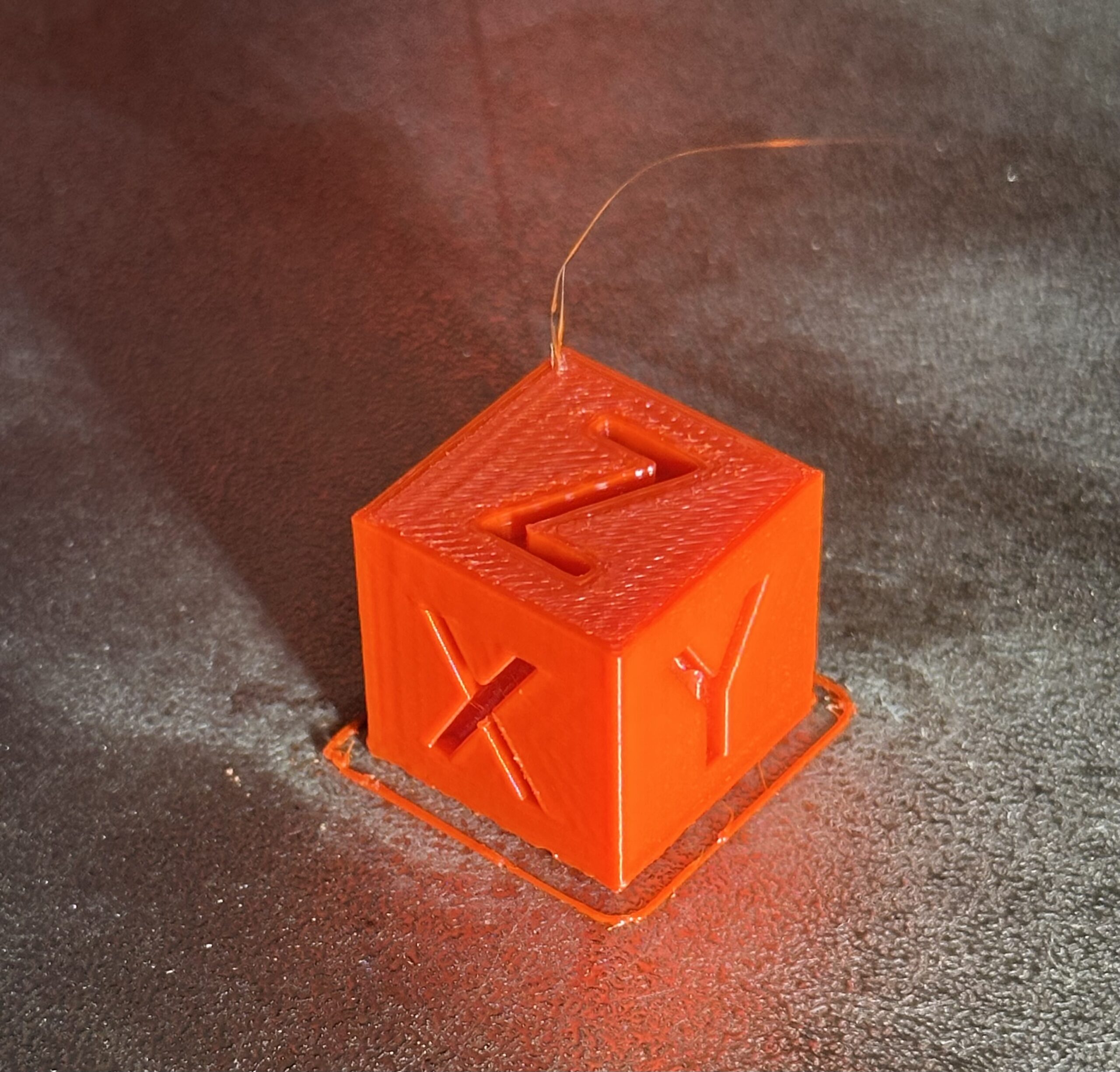
I kept things conservative and entered a value of 250 mm as my normal layer print speed in Orca Slicer and did one final test for the day, a basic calibration cube. It came out perfectly, with no need to adjust any other settings make it dimensionally accurate for my tolerances.
That is all the testing I have done so far. I still need to run a better dimensional accuracy test using Vector 3D’s excellent calibration flower. And I need to do a string and bridge test still since I’m not sure I’ve dialed in the cooling settings just right.
- Yes, the stock E3V2 can print at 200 mm/s but nowhere have I seen quality prints done at this speed nor did any of my own attempts ever come close to this. ↩︎


Recent Comments